Featured

LAB #1

Lil’ Lights

How Breadboards Work

A breadboard is a tool used to create and test out circuits. The board consists of two side sections and two middle sections. The side sections consist of two columns divided into sections of 5 holes for wires. Each column allows an electric current through all its section, but it is not connected to the other column, or the other side and middle sections. There are two columns in the side section, one marked by a red line (positive), and one marked by a blue line (negative). The middle sections consist of 63 rows of 5 holes for wires. Each row has allows a current to only flow through that specific row of 5. to connect the holes in the different rows and columns together, you must use wires. to start a circuit, one must connect the negative and positive wires of a battery to the negative and positive columns of the side sections. None of the 4 sections are connected in any way. Start building you circuit!

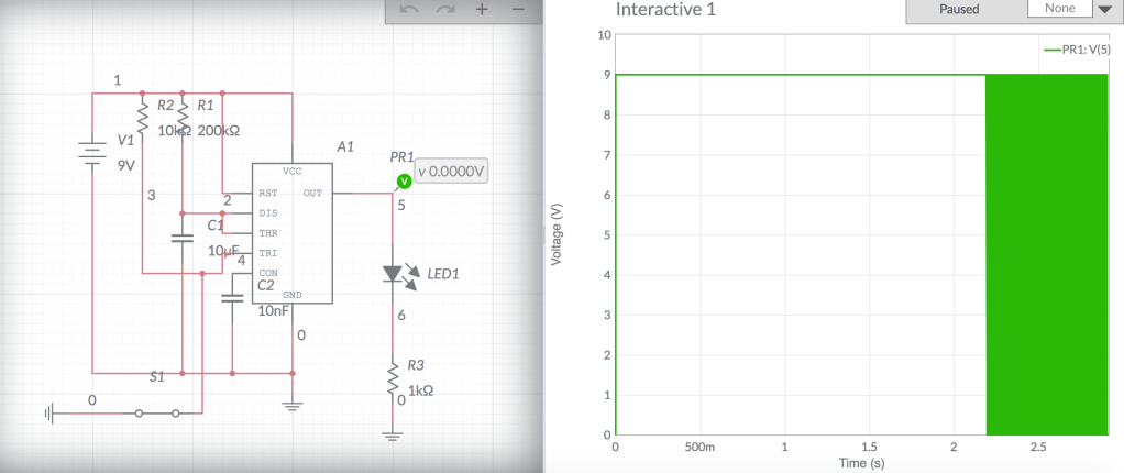
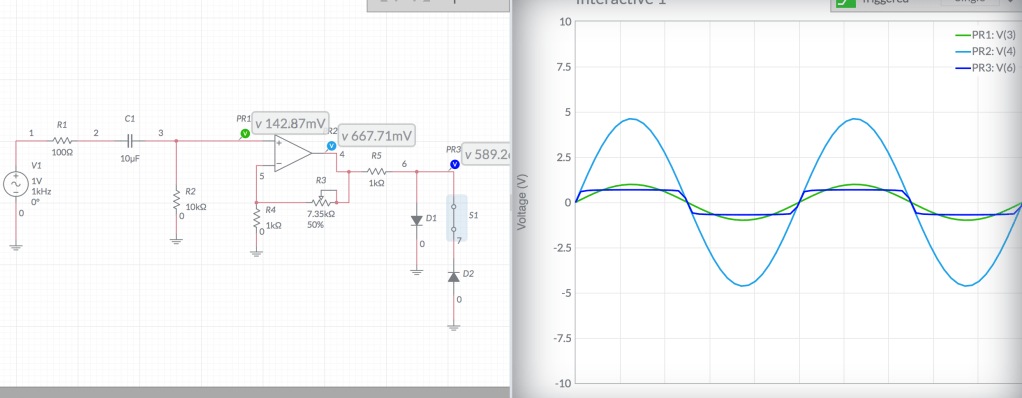
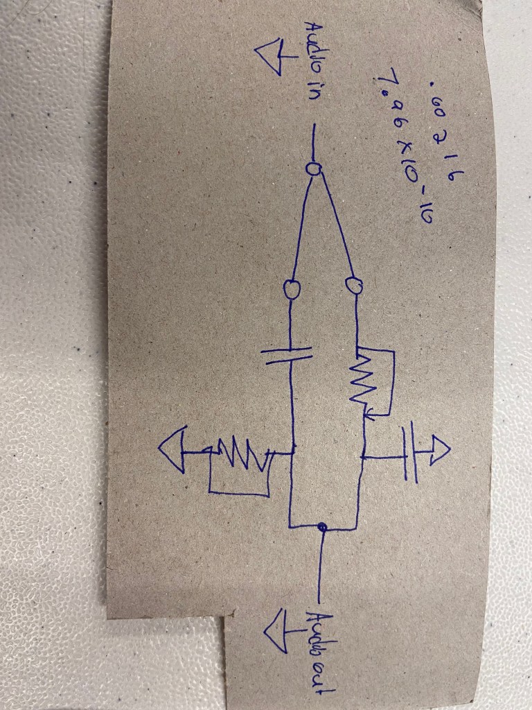
An error keeps occuring with every method I use to upload the schematics, so I will email you an image of it.

Multimeter

The multimeter is a helpful tool that is used to analyze and evaluate circuits. Multimeters have two wires, one positive and one negative, to test the levels of different aspects of a circuit. If you out the multimeter on voltage mode, it will test how many volts there are in a circuit. If you put it to resister mode, you can test how many ohms of resistance there is. If you put it on current mode, it will test how many amperes of current there is. Knowing these values, you can evaluate your circuit and determine its abilities.

List of Mistakes Made

  • I accidentally bent a wire to the point that it didn’t fit into the breadboard, so I had to cut a new wire.
  • When lighting two LEDs in the circuit, the red LED would light up, but the yellow LED would not, likely because the red was a lot warmer of a color.
  • I had to use two red LEDs
  • The photocell didn’t create as much change as I wanted it to

I did not have many issues during this process.

Inspiring Final Projects

Jillian Olesen: I thought Jillian’s project was really cool. The pedal worked really well and I liked the sound of the effect created. I though adding the filter knob made the sound so much cleaner. I like how she fused art and electronics together to make a very aesthetically pleasing pedal.

Kat McFarlane: This project was really cool because of its surprising output. I was really impressed that the synth had clear tuned polyphonically playable triad chords.

Connor Riley: This project was really cool and inspiring. It was impressive how many effects Connor was able to install into this project, and all the ways to control the effects. I want to make something at this level if I can, and then make it more aesthetically pleasing.

Lab #13

1.

Margret Sohn’s Project – This project peaked my interest because of its innovative qualities. In this project, various light shows are triggered by specific frequencies that are picked up by a microphone. If there is no frequency being inputed in to the microphone, then there are no lights, but when there is, the pitch of the sound changes the color and rhythm of the lights. Very cool!

Max Chidzero’s E-Cajon – This project stood out to me because it turned an acoustic drum into an electronic drum set. I was specifically interested in it because I have a Cajon at home, and it seems like a great project to create a more mobile and durable electronic drum set. I also thought it was great that you can switch the sample sets with the remote.

Ethan Bailey: The Singing Glock – First of all, fantastic and entertaining presentation. I don’t see this exact project as being revolutionary, but I think it can lead to something revolutionary – a voice activated piano. This project interests me because of the moving parts. Next you I want to learn how to work with moving parts in my electronics.

2.

https://create.arduino.cc/projecthub/mmackes/pool-controller-8dfa69

When the prompt told me to google any topic, I was surprised to find that I could really search up any topic, in this case, a swimming pool. This digital electronic can control the workings of a swimming pool, including aspects such as the temperature and the yard lights surrounding the pool.

This guitar pedal for an electrostrat has some really nice sounding distortion effects on it. specifically the ring the modulator, which gives the sound a sharp, buzzy, and almost creamy sound. Awesome pedal!

3.  Analog, Analog, Analog.

4. I took an introduction to computer programming class this semester, and I plan to continue taking programming classes.

Lab #12

https://www.multisim.com/content/gXNV9zfix8YgZjJp6zs9zj/monostable-multivibrator/open/

2. An example of a circuit that uses the 555 timer is a Infrared Remote Control Timer. This is used to create a signal from the transmitter circuit, which is received by the receiver circuit, within the time that the signal is present. The transmitter cur cite uses an astable multivibrator, and the receiver circuit uses a monostable receiver circuit.

Lab #11

1a. There is a lot I like about these guitar pedals. I think of the creation nd design of guitar pedals as an art form. They are colorful and portray an alt. rock music lifestyle to whomever foot is on the pedal. My my favorite effects are BOSS-DS2 turbo distortion. I also enjoy slice pedals and pitch shifting pedals.

1b. The difference between major companies and smaller pedal companies is the specificity of the pedal’s effect and the design. Companies like Boss make more simply designed pedals, and have a more comfortable on/off switch (press pad) rather than a button, which is for difficult to have control over. Also, larger companies tend to have pedals with a singular color, while boutique companies have much more intricate designs on their pedals.

1c.

This is one of the most interesting guitar pedals I have ever heard. This pedal is called the rainbow machine bu Earthquaker devices. I assume that this pedal is an oscillator/filter/pitchshifter. The pedal uses foot controlled faders to effect the direction of the sliced up “beeps and boops”. This pedal gives a hypnotic and mystical vibe to your guitar playing like you have never heard before.

2. The SPST switch is essentially an on/off switch. This switch only has one input and one outpput, so if the switch is on, the circuit is closed, and if the switch off the circuit is open.

3. A momentary button is one that stays on (closed curcuit) as long as the button is being physically compressed. A latching button remains on once it is switched or pressed on, and keeps the circuit closed until the button/switch is pressed again. You would use a momentary button to torn on a cheap keychain flashlight so the batter is conserved, and you would use a latching button to turn on a keyboard so that you can play without holding down the on/off button.

Lab #8

1. The comparator outputs a square wave and the integrator outputs a triangle wave.

2. If the Vin of an integrator is positive, it will ramp down, and if the Vin is negative, it will ramp up.

3. With a comparator, if the op amp’s + input is connected to a greater voltage that that connected to it’s – input, the op amp’s output will be about negative 9v DC.  If the op amp’s + input is connected to a lower voltage that that connected to it’s – input, the op amp’s output will be about positive 9v DC.

4. So the bigger the resistance R you use the slower the ramp gets, and the bigger the capacitor gets the slower the ramp gets.

5. You need multiple op amps to create a polyphonic synth.

Lab #5

Adding a Capacitor and Resistor

You must adfd a resistor and capacitor to the input and output of your circuit for protection. They will regulate the DC voltage in a circuit so they don’t over charge the audio input/output.

Calculations

R2 = 10k ohms

R1 = 10k ohms

Gain = 1 + (R2 / R1)

Gain = 1 + (10k / 10k)

Gain = 1 + 1

Gain = 2

Calculations

Highest – R1 = 10k, R2 = 10k

Gain = 1 + (10k / 10k)

Gain = 1 + 1

Gain = 2

Lowest – R1 = 10k, R2  = 0

Gain = 1 + (0 / 10k)

Gain = 1 + 0

Gain = 1

Calculations and Analysis

Rin = 10k

Rf = 20k

Gain = -Vin * (Rf / Rin)

Gain = -1 * (20k / 10k)

Gain = -1 * 2

Gain = -2

In this photo the output is inverted and has two times the voltage of the input.

Calculations

Highest – Rin = 5k, Rf = 10k, Vin = 1

Gain = -1 (10k / 5k)

Gain = -1 * 2

Gain = -2

Lowest – Rin = 5k, Rf = 0k, Vin = 1

Gain = -1 (0 / 5k)

Gain = -1 * 0

Gain = 0

LAB #4

Explaining the Oscilloscope

  • On the graph shown on the oscilloscope, there is an x-axis and a y-axis. The x represents time and the y represents voltage. Using the voltage per division setting on the oscilloscope, you can determine how many volts are each interval of the y-axis. Your can have .1 to 50 volts per division in this graph. In this case, the oscilloscope is set to .5 volts per division, making it 2 divisions for every volt.
  • The trigger section of the oscilloscope stabilizes the wave form shown on the graph. The trigger function will take multiple disorganized waves of one frequency from  the channel input and stabilize them as one wave form> Using the trigger function you can place where the wave is horizontally on the graph, you can select the channel that the input is coming from, the way in which the wave is shown from the channel(s), and the trigger level of the waves.
  • In the CRT section of the oscilloscope, you can fix the intensity (width of the line) level, and the focus of the line to make it more clear.
  • The power section turns the oscilloscope on and off.
  • In the Vertical section, you can set the vertical placement of the line on the graph. In this case, the line is set so that it is on the x axis. In the two channel sections, you can first choose which channel you are observing. You can set the voltage to either AC, ground, or DC (in this case both are set to DC). Using the voltage per division knobs, you can set how many volts per division the graph displays.
  • In the Horizontal section, you can set the time per division. This shows how many times the wave goes through one period. If it is two slow then the wave will flicker or not be too clear. In this case, the time per division is fast enough that the wave is perceived as stationary.
  • In electronics terms, turning the pot means turning the potentiometer. The potentiometer is almost any turnable knob on a piece of electronic equipment. Turning the potentiometer will change the resistance on a certain circuit, which will change a specific setting on the electrical equipment.

Lab #3

The First Steps of Soldering

  • Turn on the soldering iron by pressing on the switch
  • Turn the dial between 4 and 5 to get a good setting for heat
  • Take the soldering iron out of it’s holder
  • Check the tip of the iron, if it’s more shiny then it is ready to use, but if it is darkened it should be wiped off and cleaned using a damp sponge
  • The soldering iron is ready for use

Before You Step Away from the Soldering Iron

  • Clean the tip of the soldering iron by using the sponge to get rid of any residue left from your work.
  • Place the soldering iron back into the holder
  • Flip the on/off switch to turn the heat on the soldering iron off

Setting the Multimeter

When measuring with the multimeter, you must check three things.

  • The dial should be set to the correct setting. In this specific lab, the multimeter should be set to the DC settings.
  • The wires of the multimeter should be connected to the correct compartments
  • You should measure the voltage of the battery first to have a better reference for your other measurements

Lowest Possible Resistor

Battery Measured Value: 8.62 volts

USING CALCULATED CURRENT

The resistors have a power rating of .25 Watts

.25 Watts / 8.62 Volts = .029 Amps

8.62 Volts / .029 Amps = 293.79 Ohms

USING MEASURED CURRENT

Measured Current: .027 Amps

8.62 Volts / .027 Amps = 319.26 Ohms

The smallest resistor in my resistor kit that I can use is 330 ohms.

Find the Current in Series and Parallel

Battery – 8.62 Volts

R1 – 1k ohms

R2 – 1k ohms

R3 – 2.2k ohms

R4 = 3.3k ohms

1 / ( (1 / 1000) + (1 / 1000) + (1 / 2200) + (1 / 3300) ) = 362.64 ohms

8.62 / 362.64 = .0237 amps

8.62 ‘ 1000 = .0086 amps

8,62 / 2200 = .0039 amps

8.62 / 3300 = .0026

Calculated Values:

I1 – .0236 Amps

I2 – .0086 Amps

I3 – .0086 Amps

I4 – .0039 Amps

I5 – .0026 Amps

I6 – .0237 Amps

Measured Values:

I1 – .024 amps

I2 – .009 Amps

I3. 009 Amps

I4 – .004 Amps

I5 – .003 Amps

I6 – .024 Amos

Trouble Shooting

I had some issues when soldering

  • I had some trouble figuring out where to heat the chip, and where to place the solder
  • At first I added to much solder and the bulbs were connected together
  • I had to melt and scrape/pull some of the saucer out of the chip so the bulbs wouldn’t stick together
Design a site like this with WordPress.com
Get started